
Part.1 Tutorial 1
题源:Tutorial 1。参考答案与解析将按题目分块整理;若与课堂讲解或官方答案冲突,以课堂讲解或官方答案为准。

Q1 Antenna Azimuth Position Control
Section titled “Q1 Antenna Azimuth Position Control”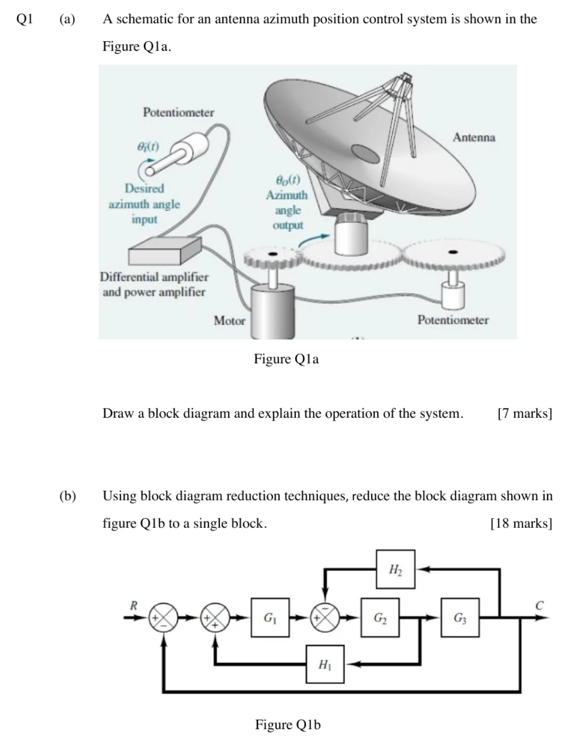
Q1(a) Block diagram and operation [7 marks]
Section titled “Q1(a) Block diagram and operation [7 marks]”A schematic for an antenna azimuth position control system is shown in Figure Q1a. Draw a block diagram and explain the operation of the system.
展示参考答案
一个合理的功能框图可以写成:
flowchart LR
  Ti["θᵢ(s)"] --> Ki["input potentiometer Kᵢ"]
  Ki --> S(("+/-"))
  S --> E["E(s)"]
  E --> Ka["amplifier K_a"]
  Ka --> Gm["motor + gears Gₘ(s)"]
  Gm --> To["θₒ(s)"]
  To --> Kf["feedback potentiometer K_f"]
  Kf -->|"-"| S
工作过程如下:输入电位器把期望方位角
若把电机和齿轮整体写成
如果输入和反馈电位器匹配,则通常有
Q1(b) Block diagram reduction [18 marks]
Section titled “Q1(b) Block diagram reduction [18 marks]”Using block diagram reduction techniques, reduce the block diagram shown in Figure Q1b to a single block.
展示参考答案
设
因为
整理
所以单一等效方框为
其中所有
Q2 Block Diagram Reduction and Design Insight
Section titled “Q2 Block Diagram Reduction and Design Insight”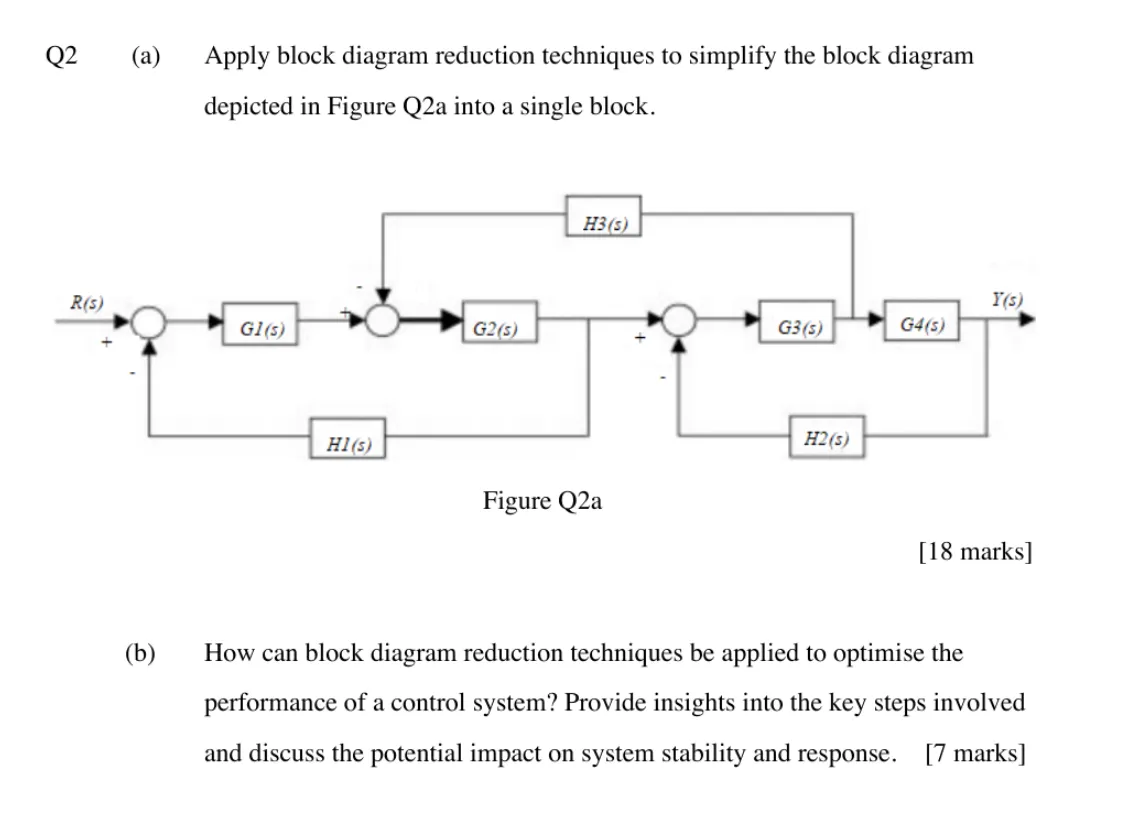
Q2(a) Reduce Figure Q2a [18 marks]
Section titled “Q2(a) Reduce Figure Q2a [18 marks]”Apply block diagram reduction techniques to simplify the block diagram depicted in Figure Q2a into a single block.
展示参考答案
设
先化简右侧反馈环:
因此
再代入中间部分:
所以
又因为
于是总传递函数为
展开分母也可写为
Q2(b) Performance optimisation [7 marks]
Section titled “Q2(b) Performance optimisation [7 marks]”How can block diagram reduction techniques be applied to optimise the performance of a control system? Provide insights into the key steps involved and discuss the potential impact on system stability and response.
展示参考答案
方框图化简的作用,是把复杂互连结构等效成一个传递函数,使系统的稳定性和动态性能可以直接从分子、分母中分析。
常用步骤是:
- 串联方框相乘:
。 - 并联方框相加:
。 - 反馈环化简:负反馈时
- 必要时移动比较点或分支点,但要保持信号关系不变。
- 得到最终闭环传递函数,并检查特征方程。
最终分母决定闭环极点,因此直接影响稳定性、阻尼、超调和响应速度;分子决定零点,会影响瞬态响应形状。通过调节控制器参数,可以降低稳态误差、改善调节时间、增加阻尼或增强扰动抑制。但增益过大或反馈结构设计不当,也可能把闭环极点推到右半平面,使系统振荡甚至不稳定。